The Sudan-based Garri Petroleum Coke Power Plant is located in the town of Algli, 70km northeast of Khartoum, Sudan, 13km east of the Nile. It is a 110MW power plant provided by the China National Machinery Import and Export Corporation to the Sudan State Power Company. There are two 240t/h fuel petroleum coke CFB boilers, two 55MW condensing steam turbines and two 55MW air-cooled generators. The power plant's main thermal control system (I&C Island) is subcontracted by the Shanghai Power Generation Equipment Design and Research Institute and provides related design, configuration, engineering, and services.
Modern thermal power generating units are increasingly complex, and the requirements for operation, control, overhaul and optimization of the units are also increasing. The traditional control concept is limited to the monitoring of major process monitoring points, while a large number of equipment are distributed and monitored locally. Management information and maintenance information are manually completed or missing, so it is difficult to implement unified and comprehensive information management for the unit, and optimize the operation of the unit. , Optimized overhaul can not play an effective guiding role.
The power plant information and control system based on the digital concept design, with its powerful intelligent field instruments and equipment, greatly expands the traditional DCS information collection and diagnosis monitoring range, so that the on-site equipment management and maintenance can be effectively obtained. information. Through high-speed communication networks, this information can be sent to the upper-level software such as plant-level monitoring information system (SIS) and information management system (MIS). At the same time, it integrates the smart transmitter management system (STMS) and the boiler furnace leak detection system (ALDS). , vibration monitoring and analysis system (VMS), weather station monitoring system (WMS), plant-wide closed-circuit television monitoring system (CCTV) and electronic patrol system (GTS), etc. provide further security, optimization, and efficient monitoring and maintenance of the unit. Guidance and protection.
The design of the instrumentation and control (I&C) system shall ensure the safe, efficient and reliable operation of the power plant under the operating procedures, ie start-stop operation, normal operation, partial load operation, emergency conditions, etc., to ensure optimal fuel supply. And reduce emission levels, operate with low cost and high efficiency.
First, the power plant control level In the Garri4 power plant uses the whole plant integration digitization idea to design the entire power plant I&C plan. The whole plant I&C mainly covers the following systems:
(1) Distributed Control System (DCS) - master control system;
(2) Safety stop system (ESD/MFT, ETS) - protection system;
(3) subcontractor control system (MPCS) - auxiliary control system (BOP);
(4) Office Network (OFFICELAN);
(5) Satellite positioning time service system (GPS);
(6) Intelligent Transmitter Management System (STMS)
(7) Continuous smoke emission monitoring system (CEMS);
(8) Boiler Tube Leakage Monitoring System (ALDS);
(9) Vibration Monitoring and Analysis System (VMS);
(10) Large-screen display system (LVS);
(11) CCTV;
(12) Intelligent Electronic Inspection System (GTS);
(13) Broadcast paging system (Paging);
(14) Weather Monitoring System (WMS);
(15) Field instruments and field control equipment;
(16) Instrumentation laboratory.
The power plant adopts an integrated DCS and necessary dedicated control equipment to control the whole plant's thermal equipment and thermal system, and to form a two-in-one management and control system for operation control and operation management. DCS provides a comprehensive, integrated and consistent system for the operation, monitoring and control of boilers and auxiliary engines, turbines and auxiliary engines, soda systems and the rest of the plant (BOP).
The power plant is equipped with a central control room (CCR), which provides a number of local control rooms or cabinets for operation, maintenance and management. All monitoring and operations can be done in the central control room.
Second, the design principle of the control system uses DCS as the power plant main control system, integrates the BOP, uses the special control device of the sub-device trader as the controller of the special-purpose equipment. Man-Machine Interface (MMD) is the operator's main monitoring interface, and does not set the conventional instrument panel (Taiwan) type of operation interface.
DCS has an operator-based LCD TFT display and human-machine interface, keyboard, and mouse operations for 4 units of 1250mm large-screen monitors for each of the two units. It has basic features such as fast response, on-line device diagnosis, and online maintenance.
The DEH and DCS use the same type of system. The DEH system can be integrated with the DCS as long as it hangs on the DCS backbone. DEH not only can share network data with DCS and complete the integration operation, but also acts as an independent controller in DCS, with relative independence.
Using ESD and safety interlocking equipment that satisfies the requirements of TK6 certification (equivalent to IEC61508SIL3), applied to the MFT of boilers and ETS of steam turbines, safety, fault tolerance, and reliability are maximized.
DCS and ESD are connected on the same Ethernet. The communication protocol, control software and configuration software are all on the same platform, so they are completely integrated.
Third, the production and management of the principle of stratification production and management are divided into three levels: the first level for the control level, it is divided into three sub-level, a direct role in the on-site production equipment monitoring; the latter two layers of production management. The layered production and management diagram is shown in Figure 1.
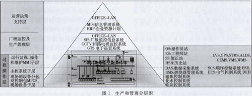 3.1 The first level - the process operation control layer The process operation control layer mainly includes the digital monitoring function for a certain equipment operation or certain operation process within the power plant, including three sub-levels: on-site equipment subcontractor control package (MPCS), main control system , operation monitoring, operation and maintenance.
Using machine, furnace, electricity integration. Some digital monitoring systems at this level are mostly relatively independent control systems. In order to fully protect the existing software and hardware investment, data operation conversion interface is added between the existing process control system and the unified planned visual power plant information platform. To achieve digital power plant compatibility with traditional process control systems.
3.1.1 On-site equipment subcontractor control package (MPCS)
These control packages are controlled by programmable logic controllers (PLCs) and special-purpose controllers based on microcomputer technology. Control equipments are generally arranged in the field cabinet room or on-site control room, including:
(1) Boiler petroleum coke fuel delivery system control package;
(2) Boiler bed material conveying system control package;
(3) Fly ash pneumatic conveying and storage system control package;
(4) chemical water treatment system control package;
(5) Compressed air preparation system control package;
(6) Stack emission continuous measurement system measurement package;
(7) Wastewater Discharge Detection System Measurement Package;
(8) Environmental testing system;
(9) Shaft monitoring system.
3.1.2 Main Control System The main control system is the core of power plant control and is controlled by DCS. DCS local control station equipment is arranged in the electronic cabinet room of the main plant operation floor; some systems can also be controlled by DCS remote I/O station as required, and the equipment is generally arranged in the field cabinet room. The contents or functions controlled by the DCS master system include:
(1) Boiler Combustion Management (BMS);
(2) Turbine speed control system (DEH);
(3) Shutdown protection system (ESD/MFT, ETS);
(4) Closed-loop control system (MCS);
(5) Data Acquisition System (DAS);
(6) Program Control System (SCS);
(7) Electrical Control System (ECS).
3.1.3 Operational monitoring, operation and maintenance The main facilities at this level are human-machine interfaces (MMDs and computer peripherals) based on personal computer technology. The operator MMI equipment is arranged in the central control room, and the DCS engineering station is arranged by the engineer in the central control room. Station indoor, set the following MMI and peripherals:
(1) Value-long management station (SS);
(2) Unit Operator Station (OS);
(3) Large screen monitoring station (MS);
(4) Engineer Station (ES);
(5) The printer.
3.2 The second level - plant level monitoring and production management This level OFFICELAN (SIS) is set for the power plant professionals, as to improve the unit operating efficiency, secondary data analysis and management use. The power plant can realize overall optimization and analysis of the real-time control system for the whole power plant based on the realization of monitoring and unified information platform for each local production process, providing operational guidance for process control; and based on the real-time status and resources of the entire power plant. Information can realize optimal allocation of resources, asset maintenance and management, etc. to achieve safe, efficient, and economical production of the whole plant. This layer can be planned for two major application systems: plant level monitoring system (SIS) and visual resource management (wide plant CCTV and security inspection system).
3.3 Level 3 - Operational Decision Support Layer This layer of OFFICELAN (MIS) is set up for plant management personnel and is used for power plant operation management. Using networking technology, several management and technical personnel's computers are connected into a local area network. Part of the operating conditions of the power plant controlled by the DCS system are transmitted to the MIS by means of remote transmission for reference by management personnel and maintenance of technical personnel. At the same time, the local area network can provide management personnel with a platform for information exchange and comprehensively analyze and analyze the real-time status, historical information, business data, and resource information data of the power plant, realizing the real-time calculation, analysis, and control of the comprehensive cost of the enterprise. Management, production, goals, and development plans provide decision support to achieve better corporate management. This is the highest level of digital power plant's role and effect.
The main equipment of MIS is OPC interface, database equipment and commercial personal computer (PC). These PCs can only see part of the power plant operating data and part of the screen, but can not operate the system. The area for setting up port devices is:
(1) Management Office;
(2) Instrument control warehouse;
(3) Instrumentation laboratory.
IV. System Optimization under the Digitalization Concept 4.1 Integrated System of DCS and PLC System The original design of the power plant's auxiliary control system (BOP), including the raw water system, fuel oil system, slag transfer system, and compressed air system, was implemented in the DCS public network. , And by the contractor control system (MPCS) of the water system, dosing system, ash handling system and petroleum coke delivery system using PLC system, and then each subsystem adopts BOP networking mode, through Modbus communication between DCS and PLC Ways to integrate into the main control system. This is a more commonly used method in domestic power plants.
Because the communication between different systems will cause the reliability to decline, according to domestic practice, MPCS is only monitored without operation in the main control system, and if it is to be operated, hard wiring is adopted; at the same time, the monitoring screens completed by different contractors are due to the style. Different and different operating software are used, which makes operation personnel training, maintenance of engineers and spare parts of equipment doubled. Therefore, these MPCSs are removed from the equipment suppliers, and the professional I&C general contractors adopt a unified DCS to complete the monitoring functions, achieving unified control equipment, unified monitor screen style, unified network system platform and unified spare parts.
The specific solution is that the dosing system is equipped with ammonia, hydrazine plus phosphate, and this control is included in the single unit DCS. The chemical water system and petroleum coke transportation system use remote control stations and are directly incorporated into the public system. In the system configuration, the water plant and petroleum coke delivery plant are equipped with independent switches and are arranged in the common system network between the electronics. They are connected to switches in the chemical plant and petroleum coke delivery plant through optical fibers to ensure the system's anti-jamming capability. During the implementation of the project, since the chemical water system and the petroleum coke transport system must be run before the main control system is put into operation, an independent engineering station (also called an operator station) is configured in each of the two systems. Before DCS was put into use, each was independently a set of small DCS. After the main control DCS was put into use, the two systems were merged into the main control DCS to form a whole.
4.2 DCS System Dual Ring Network Four Path Network Structure Redundant communication can enhance availability between interconnected systems. The simplest approach is to use a redundant system network. When a network link is damaged, the system can automatically switch to another network link. . A double-redundant system network is provided to improve system reliability. See Figure 2.
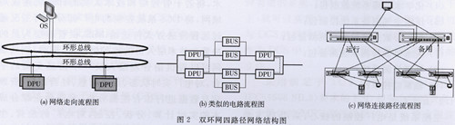
The flow chart of the network in Figure 2, the similar circuit flow diagram, and the network connection path flow chart show that: no matter which path (network device) is faulty, the system has three other paths to go, showing the high reliability of the network layer.
4.3 Integration between multiple systems under multiple levels I&C islands are installed in all offices, secretarial rooms, conference rooms, training rooms, computer rooms, warehouse managers' offices, factory floors, and other places with the above functions in the plant of the power plant. The complete LAN provides a network platform for all managers, maintenance personnel, logistical support personnel, and support personnel. At the same time, it provides a unified real-time database on the main server to collect all useful data on site for use by SIS and MIS.
In the entire system structure, the auxiliary analysis management system is integrated with the digital power plant level in the following way, as shown in Figure 3.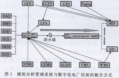 V. Conclusion During the initial design of the entire power plant, the concept of digitalization was taken into consideration in the selection and configuration of power plant thermal control equipment, and a large number of smart devices were used to manage the equipment (such as the KKS (unique) number, range setting, linear processing, etc. ) and equipment diagnostic maintenance information (such as equipment failure status, etc.) for unified management, and further upload to the upper SIS, MIS and other software.
The DCS system incorporates all plant-wide controls into its scope as much as possible, making the entire plant's control philosophy uniform.
All professional auxiliary systems conduct data analysis management, fault diagnosis or safety precautions on the one hand, and on the other hand, further upload data to the upper system for further analysis, so that each system is fully and completely integrated under the concept of digitization so that the Operational operations, management and maintenance play a guiding and facilitating role.
Modern thermal power generating units are increasingly complex, and the requirements for operation, control, overhaul and optimization of the units are also increasing. The traditional control concept is limited to the monitoring of major process monitoring points, while a large number of equipment are distributed and monitored locally. Management information and maintenance information are manually completed or missing, so it is difficult to implement unified and comprehensive information management for the unit, and optimize the operation of the unit. , Optimized overhaul can not play an effective guiding role.
The power plant information and control system based on the digital concept design, with its powerful intelligent field instruments and equipment, greatly expands the traditional DCS information collection and diagnosis monitoring range, so that the on-site equipment management and maintenance can be effectively obtained. information. Through high-speed communication networks, this information can be sent to the upper-level software such as plant-level monitoring information system (SIS) and information management system (MIS). At the same time, it integrates the smart transmitter management system (STMS) and the boiler furnace leak detection system (ALDS). , vibration monitoring and analysis system (VMS), weather station monitoring system (WMS), plant-wide closed-circuit television monitoring system (CCTV) and electronic patrol system (GTS), etc. provide further security, optimization, and efficient monitoring and maintenance of the unit. Guidance and protection.
The design of the instrumentation and control (I&C) system shall ensure the safe, efficient and reliable operation of the power plant under the operating procedures, ie start-stop operation, normal operation, partial load operation, emergency conditions, etc., to ensure optimal fuel supply. And reduce emission levels, operate with low cost and high efficiency.
First, the power plant control level In the Garri4 power plant uses the whole plant integration digitization idea to design the entire power plant I&C plan. The whole plant I&C mainly covers the following systems:
(1) Distributed Control System (DCS) - master control system;
(2) Safety stop system (ESD/MFT, ETS) - protection system;
(3) subcontractor control system (MPCS) - auxiliary control system (BOP);
(4) Office Network (OFFICELAN);
(5) Satellite positioning time service system (GPS);
(6) Intelligent Transmitter Management System (STMS)
(7) Continuous smoke emission monitoring system (CEMS);
(8) Boiler Tube Leakage Monitoring System (ALDS);
(9) Vibration Monitoring and Analysis System (VMS);
(10) Large-screen display system (LVS);
(11) CCTV;
(12) Intelligent Electronic Inspection System (GTS);
(13) Broadcast paging system (Paging);
(14) Weather Monitoring System (WMS);
(15) Field instruments and field control equipment;
(16) Instrumentation laboratory.
The power plant adopts an integrated DCS and necessary dedicated control equipment to control the whole plant's thermal equipment and thermal system, and to form a two-in-one management and control system for operation control and operation management. DCS provides a comprehensive, integrated and consistent system for the operation, monitoring and control of boilers and auxiliary engines, turbines and auxiliary engines, soda systems and the rest of the plant (BOP).
The power plant is equipped with a central control room (CCR), which provides a number of local control rooms or cabinets for operation, maintenance and management. All monitoring and operations can be done in the central control room.
Second, the design principle of the control system uses DCS as the power plant main control system, integrates the BOP, uses the special control device of the sub-device trader as the controller of the special-purpose equipment. Man-Machine Interface (MMD) is the operator's main monitoring interface, and does not set the conventional instrument panel (Taiwan) type of operation interface.
DCS has an operator-based LCD TFT display and human-machine interface, keyboard, and mouse operations for 4 units of 1250mm large-screen monitors for each of the two units. It has basic features such as fast response, on-line device diagnosis, and online maintenance.
The DEH and DCS use the same type of system. The DEH system can be integrated with the DCS as long as it hangs on the DCS backbone. DEH not only can share network data with DCS and complete the integration operation, but also acts as an independent controller in DCS, with relative independence.
Using ESD and safety interlocking equipment that satisfies the requirements of TK6 certification (equivalent to IEC61508SIL3), applied to the MFT of boilers and ETS of steam turbines, safety, fault tolerance, and reliability are maximized.
DCS and ESD are connected on the same Ethernet. The communication protocol, control software and configuration software are all on the same platform, so they are completely integrated.
Third, the production and management of the principle of stratification production and management are divided into three levels: the first level for the control level, it is divided into three sub-level, a direct role in the on-site production equipment monitoring; the latter two layers of production management. The layered production and management diagram is shown in Figure 1.
Using machine, furnace, electricity integration. Some digital monitoring systems at this level are mostly relatively independent control systems. In order to fully protect the existing software and hardware investment, data operation conversion interface is added between the existing process control system and the unified planned visual power plant information platform. To achieve digital power plant compatibility with traditional process control systems.
3.1.1 On-site equipment subcontractor control package (MPCS)
These control packages are controlled by programmable logic controllers (PLCs) and special-purpose controllers based on microcomputer technology. Control equipments are generally arranged in the field cabinet room or on-site control room, including:
(1) Boiler petroleum coke fuel delivery system control package;
(2) Boiler bed material conveying system control package;
(3) Fly ash pneumatic conveying and storage system control package;
(4) chemical water treatment system control package;
(5) Compressed air preparation system control package;
(6) Stack emission continuous measurement system measurement package;
(7) Wastewater Discharge Detection System Measurement Package;
(8) Environmental testing system;
(9) Shaft monitoring system.
3.1.2 Main Control System The main control system is the core of power plant control and is controlled by DCS. DCS local control station equipment is arranged in the electronic cabinet room of the main plant operation floor; some systems can also be controlled by DCS remote I/O station as required, and the equipment is generally arranged in the field cabinet room. The contents or functions controlled by the DCS master system include:
(1) Boiler Combustion Management (BMS);
(2) Turbine speed control system (DEH);
(3) Shutdown protection system (ESD/MFT, ETS);
(4) Closed-loop control system (MCS);
(5) Data Acquisition System (DAS);
(6) Program Control System (SCS);
(7) Electrical Control System (ECS).
3.1.3 Operational monitoring, operation and maintenance The main facilities at this level are human-machine interfaces (MMDs and computer peripherals) based on personal computer technology. The operator MMI equipment is arranged in the central control room, and the DCS engineering station is arranged by the engineer in the central control room. Station indoor, set the following MMI and peripherals:
(1) Value-long management station (SS);
(2) Unit Operator Station (OS);
(3) Large screen monitoring station (MS);
(4) Engineer Station (ES);
(5) The printer.
3.2 The second level - plant level monitoring and production management This level OFFICELAN (SIS) is set for the power plant professionals, as to improve the unit operating efficiency, secondary data analysis and management use. The power plant can realize overall optimization and analysis of the real-time control system for the whole power plant based on the realization of monitoring and unified information platform for each local production process, providing operational guidance for process control; and based on the real-time status and resources of the entire power plant. Information can realize optimal allocation of resources, asset maintenance and management, etc. to achieve safe, efficient, and economical production of the whole plant. This layer can be planned for two major application systems: plant level monitoring system (SIS) and visual resource management (wide plant CCTV and security inspection system).
3.3 Level 3 - Operational Decision Support Layer This layer of OFFICELAN (MIS) is set up for plant management personnel and is used for power plant operation management. Using networking technology, several management and technical personnel's computers are connected into a local area network. Part of the operating conditions of the power plant controlled by the DCS system are transmitted to the MIS by means of remote transmission for reference by management personnel and maintenance of technical personnel. At the same time, the local area network can provide management personnel with a platform for information exchange and comprehensively analyze and analyze the real-time status, historical information, business data, and resource information data of the power plant, realizing the real-time calculation, analysis, and control of the comprehensive cost of the enterprise. Management, production, goals, and development plans provide decision support to achieve better corporate management. This is the highest level of digital power plant's role and effect.
The main equipment of MIS is OPC interface, database equipment and commercial personal computer (PC). These PCs can only see part of the power plant operating data and part of the screen, but can not operate the system. The area for setting up port devices is:
(1) Management Office;
(2) Instrument control warehouse;
(3) Instrumentation laboratory.
IV. System Optimization under the Digitalization Concept 4.1 Integrated System of DCS and PLC System The original design of the power plant's auxiliary control system (BOP), including the raw water system, fuel oil system, slag transfer system, and compressed air system, was implemented in the DCS public network. , And by the contractor control system (MPCS) of the water system, dosing system, ash handling system and petroleum coke delivery system using PLC system, and then each subsystem adopts BOP networking mode, through Modbus communication between DCS and PLC Ways to integrate into the main control system. This is a more commonly used method in domestic power plants.
Because the communication between different systems will cause the reliability to decline, according to domestic practice, MPCS is only monitored without operation in the main control system, and if it is to be operated, hard wiring is adopted; at the same time, the monitoring screens completed by different contractors are due to the style. Different and different operating software are used, which makes operation personnel training, maintenance of engineers and spare parts of equipment doubled. Therefore, these MPCSs are removed from the equipment suppliers, and the professional I&C general contractors adopt a unified DCS to complete the monitoring functions, achieving unified control equipment, unified monitor screen style, unified network system platform and unified spare parts.
The specific solution is that the dosing system is equipped with ammonia, hydrazine plus phosphate, and this control is included in the single unit DCS. The chemical water system and petroleum coke transportation system use remote control stations and are directly incorporated into the public system. In the system configuration, the water plant and petroleum coke delivery plant are equipped with independent switches and are arranged in the common system network between the electronics. They are connected to switches in the chemical plant and petroleum coke delivery plant through optical fibers to ensure the system's anti-jamming capability. During the implementation of the project, since the chemical water system and the petroleum coke transport system must be run before the main control system is put into operation, an independent engineering station (also called an operator station) is configured in each of the two systems. Before DCS was put into use, each was independently a set of small DCS. After the main control DCS was put into use, the two systems were merged into the main control DCS to form a whole.
4.2 DCS System Dual Ring Network Four Path Network Structure Redundant communication can enhance availability between interconnected systems. The simplest approach is to use a redundant system network. When a network link is damaged, the system can automatically switch to another network link. . A double-redundant system network is provided to improve system reliability. See Figure 2.
The flow chart of the network in Figure 2, the similar circuit flow diagram, and the network connection path flow chart show that: no matter which path (network device) is faulty, the system has three other paths to go, showing the high reliability of the network layer.
4.3 Integration between multiple systems under multiple levels I&C islands are installed in all offices, secretarial rooms, conference rooms, training rooms, computer rooms, warehouse managers' offices, factory floors, and other places with the above functions in the plant of the power plant. The complete LAN provides a network platform for all managers, maintenance personnel, logistical support personnel, and support personnel. At the same time, it provides a unified real-time database on the main server to collect all useful data on site for use by SIS and MIS.
In the entire system structure, the auxiliary analysis management system is integrated with the digital power plant level in the following way, as shown in Figure 3.
The DCS system incorporates all plant-wide controls into its scope as much as possible, making the entire plant's control philosophy uniform.
All professional auxiliary systems conduct data analysis management, fault diagnosis or safety precautions on the one hand, and on the other hand, further upload data to the upper system for further analysis, so that each system is fully and completely integrated under the concept of digitization so that the Operational operations, management and maintenance play a guiding and facilitating role.
Anti-Glaring Diffuser Sheet,Anti Glaring Sheet,Glare Control Plate,Lighting Reflector
Jiangmen Kunxin new Material Technology Co.,Ltd , https://www.kunxinplastics.com