Abstract: With the rapid development of science and technology, power supplies with inverter functions such as inverters, intermediate frequency circuits, and ups power supplies are widely used in industrial production fields, and their abnormal operation will have different degrees of influence on other devices. Therefore, in the actual equipment installation, maintenance and use, we must pay more attention to the impact between different devices. This article mainly introduces the abnormal voltage analysis and processing of the power grid caused by the output grounding of the frequency conversion device for readers to refer to.
1. Failure phenomenon The 3rd-phase calcining 4# rotary kiln of Aluminum Qinghai Branch was newly built in May 2005, and its petroleum coke calcining capacity is 12t/h; the large-kiln drive system adopts the frequency converter (Siemens) speed control. The normal production of the amount of material generally controlled in the range of 10 ~ 11.6t / h, the frequency converter (110va) operating frequency is set in the range of 38 ~ 46hz, the large kiln drive motor is an ordinary three-phase asynchronous motor (model y315s-6 , 75kw), the load current between 68 ~ 92a; stop material cooling period, the large kiln operation in ultra-low speed state (kiln body speed working in the range of 2.5 ~ 2.9r/min), the inverter operating frequency is about 5hz. At 8 o'clock on the morning of June 18th, 2006, the material was stopped and cooled down. Due to the maintenance task of the small kiln, the large kiln stopped the kiln insulation after running for more than one hour at a low speed. At 3 o'clock in the afternoon, during the start-up process of the large kiln drag motor, some low-voltage devices in the operating room (such as emergency lighting lamp chargers, chargers for intercom chargers, and displays, etc.) suddenly appeared smoke, and the operator immediately terminated the large kiln frequency conversion device. After starting the operation, the anomaly disappeared immediately. According to the on-site operator's description of the anomaly, the preliminary analysis may be caused by a sudden increase in the voltage of the power supply system. However, the voltage of each phase of the power supply system is normal (phase voltage is 220v). Check the console and the control cabinet. There is a noticeable burnt smell in the cabinet and a number of indicator burnouts, ups tripping, PLC and belt measurement are found. Power modules such as scales are burned. Due to the abnormal phenomenon occurred during the start-up of the rotary kiln dragging frequency conversion device, check the large kiln control inverter has not found abnormal (panel display is normal, electronic devices are not damaged and other signs); check the power supply system transformer neutral (zero line) , No abnormal problems such as poor contact (sometimes the contactor's zero line connection point is in poor contact or overheated, will cause zero potential shift on the neutral line). Then, when the kiln inverter was restarted, the above abnormal phenomenon immediately appeared. Since various monitoring measures were taken before the operation, the measured single-phase voltage of the power supply system rose to about 286v after the inverter was started; the inverter brake (released The electric energy) resistance is automatically put into operation (the brake resistor working sound can be heard), and the measured braking resistor temperature is 72°C (circumferential temperature 19°C); after the large kiln inverter is started and stopped, the grid voltage returns to normal (220v). Due to the frequency conversion start-up process (starting process lasted for 4~6s), the kiln body shows no signs of rotation, so check the motor, open the junction box and find that the winding turns black and there is a strong odor inside the casing. Measure the three-phase winding of the motor on the ground. Insulation resistance is 0, 12mω and 16mω respectively.
2. Fault Analysis In actual work, the voltage rise of the power supply system caused by the insulation damage of the inverter drive motor is extremely rare, and it is difficult to explain with general knowledge of electrotechnics. In response to this phenomenon of abnormal voltage rise in the power supply grid, we conducted a comprehensive on-site inspection and measurement. The measured grounding protection line of the motor was connected to the neutral line (neutral line) of the power supply network (resistance was 0 Ω). Further investigation revealed that the kiln motor was grounded. The protection line is connected to the cabinet body of the inverter, and the cabinet body is connected to the neutral line of the power supply system (as a measure of protection and zero connection). This grounding line and the neutral line constitute the repeated grounding of the electrical equipment (also known as loop-type repetitive grounding). Its role is to reduce the risk of electric shock when the grounding wire is disconnected or when the resistance of the grounding body is large. At the same time, when the charged part of the equipment touches the shell, the short-circuit current forms a loop through the neutral wire, which can accelerate the action of the circuit protection device. The mechanism of the abnormal phenomenon is analyzed as follows: When the insulation of one phase winding of the motor controlled by the inverter device is damaged (breakdown), if the inverter is started, the three-phase AC (low frequency) voltage output by the inverter will pass through the motor to control the power line. , motor core, grounding line, power supply system neutral line (zero line) superimposed on the Power Transformer low-frequency side power frequency (50hz) three-phase power supply. Because the frequency converter and the power transformer form a large current path through ground lines, neutral lines, and other power lines, the frequency and the initial phase of the three-phase AC voltage output by the inverter are different from the power grid voltage. This causes the superposition of different frequency power supply voltages, and the degree of superposition is closely related to the capacity of the frequency converter, the operating frequency, the initial phase, and the capacity of the power transformer. The larger the capacity of the inverter, the greater the load current at startup, and the higher the voltage after superimposition, the more serious the damage will be. The current loop formed by the inverter, grid, neutral line, and ground line is shown in Figure 1.
According to the principle of power superposition, in the case of a current path, the power supplies with different amplitudes, frequencies, and initial phases of the two AC voltages will mutually superimpose, and the voltage waveforms of the two power supplies will change greatly [1 ] (The peak value of the voltage waveform and the effective value change accordingly.) Since the frequency converter is a device that rectifies, filters and inverts three-phase AC voltages of industrial frequency into three-phase AC voltages of different frequencies. Its frequency changer is equivalent to an independent power source, its output voltage waveform initial phase, the frequency is different from the power frequency power supply electrical network; In the frequency changer during starting, its voltage frequency which the output of the inverter changes slowly from 0hz the course. Therefore, when the insulation of the single-phase winding of the dragging motor of the 4# rotary kiln is broken down, the winding of the power supply transformer, the conductors of the inverter motor (including the power line and the core), the grounding wire, and the power grid neutral wire constitute a current path. When the inverter is started, it will cause the low-frequency AC voltage of 0~50hz output from the inverter to be superimposed on the AC voltage of 50hz of the power supply system, causing the three-phase power supply voltage of the power supply grid to rise to 286v, causing single-phase (220vac) electrical appliances to work. The voltage is too high, and overheating (smoke) or burnout failure occurs. At the same time, as the input AC voltage of the inverter increases, the rectified DC voltage will inevitably increase. Therefore, the DC overvoltage protection circuit of the inverter will start automatically. (ie put brake resistors to consume power). 5hz AC voltage waveform (inverter output low frequency) and 50hz AC voltage waveform (grid power frequency) superposition, the principle shown in Figure 2.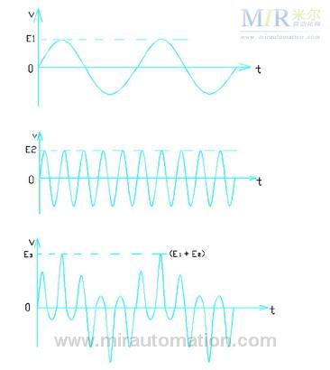
(a) Inverter output b' phase voltage waveform (220v5hz) (b) Power supply a phase voltage waveform (220v50hz) (c) a, b Superimposed power grid a phase voltage waveform Figure 2 Inverter output b' phase voltage and power supply network a phase voltage waveform superposition principle Figure 2a) for the inverter output b' phase AC voltage waveform, the peak waveform is e1 (measured effective value is about 220v), frequency is 5hz (optional The other waveforms with different frequencies are superimposed with the same result.) Figure 2b) is a phase-frequency AC voltage waveform of the power supply system. The peak value of the waveform is e2, the frequency is 50hz; Figure 2c) is the b' phase of the inverter output (5hz Waveforms that are superimposed on the a-phase of the power supply grid. The peak value of the superimposed waveform increases from e1 before superposition to e1+e2, and its corresponding voltage rms value must also increase; the waveform results of the voltage waveforms of phase b and c of the power supply system superimposed with each other are the same as the phase a. Only the initial phase of the superposed waveform peak is different, but the effective values ​​are equal [1].
3. Troubleshooting The 4# rotary kiln motor of our factory is an ordinary three-phase asynchronous motor. Since the inverter runs at ultra-low frequency of 5hz for a long time, its motor cooling fan runs at a low speed, and the cooling air flow of the motor is greatly reduced. The motor is overheated and the motor stator winding insulation is burned out. After replacing the motor, the large kiln control inverter was started many times, and there was no increase in the grid voltage.
In order to prevent similar faults from causing voltage system abnormality to occur again, we have adopted a protective zero-crossing line for disconnecting the body of the 4# rotary kiln (including the motor grounding wire), as shown in Figure 3. Make the transformer neutral line (neutral line) of the power supply system and the kiln body grounding line independent of each other (actually through the earth but still have a large resistance), and ground the two devices separately so that the grounding wire of the equipment is There is no large current path between the neutral lines of the power supply system. It can avoid the phenomenon that the voltage of the power grid system rises after the output of the inverter device is grounded. In practice, when the frequency conversion device is grounded, its grounding current forms a loop through the grounding line, ground, and the neutral line of the power supply system. The superimposed voltage drop (increase) is entirely or partially borne by the earth. However, the power supply system, frequency conversion equipment, and other electrical energy equipment will not significantly increase the voltage. In order to prove the reliability of this processing result, we carried out a fault simulation test, and started the inverter device through one phase of the inverter, and measured the three-phase power supply system has no change to the ground voltage during the inverter startup process. The brake resistor also does not appear to work automatically.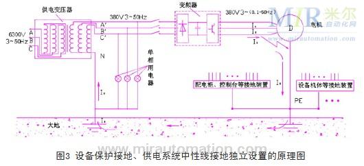
4. Concluding remarks With the rapid development of science and technology, power supplies with inverter functions such as inverters, intermediate frequency circuits, and ups power supplies are widely used in industrial production fields, and their abnormal operation will have different degrees of influence on other devices. Therefore, in the actual equipment installation, maintenance and use, we must pay more attention to the impact of different equipment, only a comprehensive understanding of each other's role, take the necessary precautionary measures to ensure the safe and reliable operation of all equipment.
TL Series ,Corrugated Steel Sheets ,Silicon Steel Grades ,Grain Oriented Electrical Steel
Roller Bearing Co., Ltd. , http://www.nbballast.com